The Modular Sub System (MSS) Overview
- Mar 13, 2020
- 6 min read
The Modular Sub System (MSS) Overview

I have a detailed video overview of this system on my YouTube channel. Feel free to take a look here. There is a lot of additional information that I included in the video, so I do urge you to take a look!
One of the challenges with large RC submarines is the creation of a control and command system that can handle propulsion, control and buoyancy in such a large scale.

Historically, most builders will pursue what is called the "dry hull method". In this setup, a large portion of the boat is sectioned off as a completely dry section and the electronic components are housed within in. The advantage is that this results in a huge amount of open volume to install components, allowing for easy installation and access. The downside, however, is that sealing the very large lids for these sections is problematic and often time-consuming to gain access to and seal up again. Additionally, the creation of such a large sealed volume means that these boats have a tremendous amount of buoyancy which needs to be offset by the installation of copious amounts of fixed ballast. This results in tremendously heavy models that are difficult to transport, launch and retrieve.
Watertight cylinders are the traditional alternative to dry hull boats, however they don't lend themselves well to large scale submarines. Sealing very large diameter tubes reliably and in a manner that is easy to access is challenging, as is housing the larger batteries and components required by much larger models.
An alternative to these two construction methodologies is something that I call the "Modular Sub System" or MSS for short. My version of this system was inspired by a gentleman by the name of Ed Tordahl, who constructed a large-scale 1:48 USS Skipjack model using a variation of this method.
I took his experience, added in my own, and came up with the following solution.
MSS Overview
The idea behind the MSS is utilizing a series of segregated, modular watertight compartments, each one grouped by function and/or location in the boat. Making these sub-sections modular and separate allows for installation in the most advantageous location in the boat, keeps damage caused by watertight integrity failure limited, and allows for much easier maintenance and upgrading at later times.
In my preliminary project, the system is composed of three primary modules, however there is no theoretical limit to the number that you can employ, depending on your model and what you're trying to achieve. Each main module is built from a high-strength polycarbonate waterproof case. These cases are completely waterproof, tested in excess of 80ft depth out-of-the-box. Module penetrations such as linkages and drive shafts are installed by drilling holes in the thick walls of the case and installing high-quality cup seals to seal the shaft. Access to the interior of the modules is gained by simply flipping open two latches and opening the lid. This is much different than the traditional dry hull boats that use dozens (and dozens) of nuts to hold down the lid.
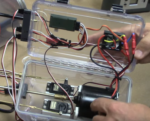
1.) Stern Drive Module: This module houses the radio receiver, the main drive motor, the motor ESC and two servos, one for rudder and one for the stern dive planes.
Receiver: My radio system of choice in this case was the excellent VEX 6-channel package, available for purchase at the Nautilus Drydocks (www.nautilusdrydocks.com)
Main Drive Motor: This was the blower motor from a vehicle's air conditioning system, purchased at a surplus store. It is approximately 3" in diameter, run direct-drive to the main propeller. It is high-efficiency with internal noise suppression, turning at approximately 5,000rpm.
ESC: I utilized the Mtroniks SUB10, 40A ESC with integrated BEC
Servos: I used standard Futaba S3004 servos

2.) Main ballast tank: This was a large, two-compartment ballast tank. The ballast system is based on an air-pump and was modeled after the excellent Semi-Aspirated Sub System (SAS) originally engineered by David Merriman and integrated into our line of SubDrivers and MSD cylinders. Venting is achieved via an electronic solenoid valve mounted at the top of the tank.
Ballast tank: The ballast tank was fabricated from a pair of clear plastic paint cans, each 1 gallon volume. They were mounted with the bases together, holes drilled in the bases to allow for the pass-through of air and water. The "tops" face outward, allowing the builder to remove them for full access to the interior of the entire ballast tank.
Solenoid valve: 12V, normally closed solenoid valve, 1/8" aperture

3.) Forward pump module: This module houses the main ballast air pump, pressure equalization valve, electronic ballast switch, and fairwater (forward) dive plane servo.
Main air pump: 12V diaphragm pump capable of pumping the full 2 gallon ballast capacity in approximately 60 seconds (as tested)
Pressure equalization valve: This was fabricated from a simple Schrader (air) valve. A micro servo depresses the valve to equalize pressure. The linkage arm is composed of a brass tube that slips over the valve stem to keep it centralized and aligned. An internal pin depresses the valve stem.
Electronic ballast switch: This is an electronic switch, an Mtroniks HP-Switcher. This allows for control over two separate electronic circuits, one for the air pump and one for the vent solenoid. This is controlled from a single RC channel.
Dive plane servo: A standard Futaba servo with a linear servo adapter attached (due to mounting location being close to the module wall).
The forward module also has the capability of being connected via a small diameter air hose to any of the other modules or a separate empty air module. This allows for much longer blow cycles without the pump stalling, as the effective volume of the pump module is added to by each of the connected containers.
The modules are connected by servo extension wires, waterproofed from water contact with a simple dab of dielectric grease. Main 12V power comes from a 12V sealed lead-acid battery that sits in the wet free-flooding part of the submarine hull.
The Ballast System
The ballast system operates in the following manner:
1.) From surfaced state, the electronic vent solenoid is opened. Air escapes the ballast tank through the valve, and water flows into the ballast tank through a series of large holes in the bottom of the tank.
2.) When the model reaches the desired state of buoyancy, the vent valve closes
3.) To surface, the blow command activates the air pump in the forward dive module. The pump draws air from the module itself and pumps it through a hose into the bottom of the ballast tank. This creates an increasing vacuum in the forward module until this vacuum overcomes the ability of the pump to draw any more air. By the time this happens, however, the pump has moved a large volume of air into the ballast tank, creating a state of positive buoyancy in the model. The model rises until the sail breaches the surface. The air intake for the ballast system is mounted in the top of the sail, capped with an inverted u-shaped fitting that prevents water from entering the tubing. Once the operator visually confirms that the model's intake is above the water's surface, they command an equalization and the equalization valve is opened. This allows the vacuum from the dive module to draw air from the surface until pressure is normalized throughout the system. From that point, the air pump can continue to blow the main ballast tank, drawing air through the equalization valve from the surface to do so.
Once the model reaches full surfaced waterline, the equalization valve is closed and the model is ready for the next submerging process.
Note that this system, unlike an enclosed system such as a piston or sealed pump version, does not allow for unlimited cycling of the ballast system without surfacing and equalizing the air pressure. Fortunately, doing so takes only a few seconds of the sail breaching surface and the equalization valve being opened.
Parts List and Suppliers: (Description / Amount / Unit Cost / Extended Cost / Supplier)
Robart air reservoir1$19.45$19.45Robart Manufacturing
Misc. rubber hose and wire1$12.00$12.00Amazon
Clear paint cans set2$12.00$24.00Amazon
Vent Solenoid1$12.65$12.65Amazon
Sealed Lead Acid 12V battery1$15.99$15.99Amazon
S3 T2500 Clear Case1$25.75$25.75Amazon
S3 T3500 Clear Case1$30.99$30.99Amazon
Air Pump1$19.99$19.99Amazon
Small Servo1$1.78$1.78Amazon
Large Servos3$13.98$41.94Amazon
HP Switcher Unit1$52.88$52.88Nautilus Drydocks
VEX 6-channel radio1$253.00$253.00Nauitlus Drydocks
Drive motor1$10.00$10.00Surplus Store
ESC1$4.00$4.00Nautilus Drydocks
AD2 pitch controller1$59.99$59.99Nautilus Drydocks
Seals4$8.00$32.00Nautilus Drydocks
Total:$616.41
In conclusion, I am very excited to look at implementing this system in future builds of large scale submarines where interior volume allows for the installation of the waterproof boxes. The system has numerous advantages and very few disadvantages. It is easily customizable, flexible and fairly cost-effective.
If you have questions, or comments, I'd love to hear from you! Please email me at any time.
Thanks for your time!
Bob Martin The RCSubGuy bob@rc-sub.com


Comments